
Nicholas A. Slobozien
Architectural Engineering
Construction Option
Palmyra, PA
General Building Information
Building Name: Community Hospital (fictitious)
Location and Site: 123 Community Drive Palmyra PA, 17078 (fictitious)
Building Occupants Name: Community Hospital (fictitious)
Occupancy or Function Types (type of building): Hospital
Size (total square feet): 155,000 SF
Number of Stories: 10 Stories (1 below grade, 3 existing floors, & 6 new floors)
 Building Picture - Render |
|---|
 Patient Room Headwall |
 Patient Room Footwall |
 Nurses Station |
 Elevator Lobby |
 Corridor View |
 Care Givers |
 Patient Room |
Primary Project Team:
Owner:

Architect:
Construction Manager:

Structural Engineer:
Interior Designer:

MEP Engineering:
Civil Engineering:
Landscape Designer:

Fire Protection:
Life Safety Engineering:


Helipad Design:
Building Overview:
Community Hospital (CH) is a non-profit hospital focusing on the well-being of its patients through exceptional service and testing. Consistently, Community Hospital has been recognized regionally and nationally for its clinical excellence and patient safety. Services provided by the Community include inpatient, outpatient, and radiology, as well as laboratory and pulmonary function testing. Community Hospital currently has a total of 533 inpatient beds, with 142 being semi-private rooms. Single patient rooms are now the standard for new construction of acute-care facilities. Private patient rooms allow for the ability to reduce infection, further help nurses, doctors, and healthcare workers to perform their jobs more efficient and effective, provide more privacy, and grants families the ability to support and help in the healing process. With this movement to private patient rooms, Community Hospital wants to continue its success in the healthcare industry with a six (6) story addition.
The new construction of the Community Hospital is a six story addition to the existing three (3) story section of the facility. This addition will added 66 private patient rooms with additional space for when demand requires. Once these rooms become available to the hospital 71 semi-private rooms located throughout the building will be convert to private rooms. This construction will not change the number of total beds. It will however provide additional office space, other medical uses, and the space for 80 new beds as the future demands them. With this addition Community Hospital continues to add to its unprecedented reputation and continual growth toward the future.
Major National Model Codes:
Pennsylvania Uniform Construction Code
2009 International Building Code (IBC), excluding Chapter 11
2012 International Building Code (IBC), Chapter 11, Accessibility, and Appendix E
2009 International Fire Code (IFC)
2009 International Existing Building Code (IEBC)
2009 International Mechanical Code (IMC)
2009 International Plumbing Code (IPC)
2008 National Electrical Code (NEC)
2009 International Energy Conservation Code (IECC)
2012 Life Safety Code (NFPA 101)
ANSI A117.1
NFPA 418-2008
Title 34, Part XIV, Chapter 405
Zoning Code:
The Code of the City of Lancaster
Historical Requirements:
Not Applicable
Building Enclosure
Exterior Walls:
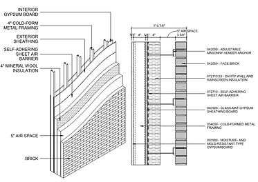
Community Hospital exterior wall system consists of six (6) varying wall configurations with similar assembly. A majority of the wall systems are based on two assemblies with varying thicknesses, materials, and features. The two (2) assemblies are brick veneer on cold formed metal framing back up wall system and EIFS system on cold formed metal framing back up wall system. The materials used in the first wall assembly includes face brick, adjustable masonry-veneer anchor, air space, cavity wall and rain-screen insulation, self-adhering sheet air barrier, glass-mat gypsum sheathing board, cold-formed metal framing, and moisture-and-mold-resistant type gypsum board. The second wall assembly consists of water-drainage exterior insulation and finish system (EIFS), water-resistive coating, glass-mat gypsum sheathing board, cold-formed metal framing, and moisture-and-mold-resistant type gypsum board. See details below for clarification on the six (6) wall assemblies.


Exterior Windows:
The Community Hospital incorporated a multitude of windows on its exterior. This is through glazed aluminum curtain wall systems to both the north and east elevations. The south elevation incorporates a storefront system of glazed aluminum window design as these will primarily be private patient room windows. These two (2) systems will both utilize two types of glazing; clear and spandrel.
Exterior Windows:
There are two type of roof system used on the Community Hospital. Both are Ethylene Propylene Diene Monomer (EPDM) roofing system with a four (4) inch minimum thickness of rigid insulation. See detail below for clarification on the two (2) systems.


Sustainability Features:
Many of the sustainable features of the Community Hospital project have been value engineered out due to budget constraints. Further research is being conducted to see if any MEP systems are being utilized in the building.
Primary Engineering Systems
Construction:
The Community Hospital Addition consists of six new floors that will be constructed on the existing building which is currently two floors plus a ground floor and a basement. The project is a 155,000 square foot addition to the existing hospital that is currently under construction to improve patient and hospital facilities. This addition is approximately $52 million dollars, creating 66 private patient rooms and additional space for when needed. The fourth and fifth floors will be constructed as shell space, while floors six, seven, and eight will be fit out as a medical/surgical space for single patient rooms, housing 20 beds on each floor. The third floor will be the main mechanical room for the tower. Once these rooms become available to the hospital, 71 semi-private rooms located throughout the building will be converted to private rooms. This construction will provide additional office space, other medical uses, and the space for 80 new beds to meet future demands. The existing ground, first, and second floors will also be expanded to the east and south. These expansion areas will be constructed as shell space under this project.
Community Hospital overbuild project utilizes the delivery method of design-bid-build. Through this process Benchmark Construction was awarded Construction Manager (CM). The staffing plan for Benchmark on the Community Hospital overbuild project follows a typical organizational layout. At the top, you have the support from the President of the Company, Mike Callahan; continuing down to the superintendents, Troy Boyer and Steve Spade. Benchmark utilizes both its field and office staff in providing the superior Construction Management services they have become known for. The project executive for this project is Christopher Flynn, and the project manager is Ryan McCreary. These two are responsible as the main point of contacts between the owner and the field. The early stages of design for the Community Hospital addition started in February 2016, with extensive ICRA measures starting June 2016 and continuing throughout the project as needed. These measures are extremely important in a healthcare setting to ensure that the hospital maintains proper clinical health code requirements. Foundation and structural erections will occur in July 2016 and May 2016 respectively. The building envelope is scheduled for December 2016 with the intention of interior fit-out occurring in July 2017. The expected completion date for the hospital addition is set for June 2018.
The Community Hospital addition is located in the southeast quadrant of the site at the intersection of North Street and East Street. The soil on which the building stands can handle a bearing capacity of 20,000 psf, with a maximum existing foundation capacity of 900 kips. Bedrock was discovered at a depth of less than 25 feet, with a soil properties consisting of surficial materials. These soils comprise of sandy silt with gravel, lean clay with gravel, and sand. From these findings it was discovered that structural steel shoring would be needed to support the additional floors. Besides the additional supports, constrictions of the site greatly affect the construction process. This is largely due to the location of the project, which is at the intersection of two streets. Both streets are one way and are heavily used, posing strains on both deliveries, laydown, set-up, and contractor parking. To accommodate these constraints all contractor parking will be at a neighboring parking lot within walking distance to the site. To deal with deliveries the schedule will be relied on heavily to assure that supplies are offloaded and dispersed to the correct areas as to not cause obstructions to daily traffic. Existing utilities are another constraint that will need to be handled with the utmost care as to not disrupt the daily hospital activities. Existing underground sewer, electric, gas, water, and above ground electric are all prominent around the site. Some changes to these systems will have to be made to accommodate for the addition.
Mechanical:
The Community Hospital Addition mechanical systems will be fed and supported by an infrastructure upgrade project named The Energy Center project, currently under construction and scheduled for completion in the spring of 2017. The upgrade of the existing chilled water and steam systems serving the entire Community Hospital. The proposed building expansion heating and cooling loads were taken in to consideration in the design of The Energy Center systems. Line size requirements for chilled water and steam were coordinated with the concurrent upgrades to the Central Energy Plant. Connection points for these services have also been coordinated with the concurrent project and the expansion will require upgrades to the equipment and piping distribution of heating hot water, plumbing, and medical gas systems.
The existing Community Hospital air handling units (Ex. AHU-201 & Ex. AHU-202), located on the roof above the Third Floor of the project site, and Ex. AHU-104 located in the Basement of the section of the addition have been removed and will be replaced under this project by two 50,000 cfm custom air handling units (AHUs) located in the third floor mechanical room. The units are near the end of their life and due to the proposed additions and renovations are undersized to support the program. The replacement of these units with larger air handling units will also allow the Owner to change space function and acuity levels on some of the existing areas on the Basement, Ground, First, and Second Floors of the building. Capacity will be provided in these two locations to serve the airflow requirements of the entire building (Basement thru Eighth floor).
The new HVAC systems, including two (2) new custom fabricated air handling units and two (2) new exhaust fans, are required to provide additional capacity for the proposed program, as well as provide additional air handling unit capacity for the addition. The units will be located in the third floor mechanical room.
Cooling for IT rooms will be provided by two pipe variable refrigerant flow (VRF) equipment. Each IT room on every floor will be provided with an individual cooling unit with condensers located on the roof of the building.
Two (2) Airborne Infectious Isolation Rooms are programmed for each floor of the addition. A common exhaust duct riser along the west side of the building will serve the Isolation Rooms, and ducted to a dedicated redundant exhaust fan system with nozzles to safely propel fumes up and away from the building at a safe velocity to avoid air re-entrainment.
MATERIALS AND METHODS:
All equipment, piping, and ductwork will be insulated in accordance with standard practices. Exposed insulation within accessible shafts, equipment rooms and the penthouse will have an additional PVC or canvas jacket.
All equipment and piping systems will be identified using a system of pressure sensitive colored labels and nameplates. The labeling systems will be in accordance with the hospital’s standards. All equipment will be isolated from the structure with vibration isolators and flexible connectors. The centrifugal fans within the air handling units will have concrete inertia bases. Valves will be provided through all piping systems to isolate all equipment, main branches and risers.
All systems will be commissioned, tested, and balanced in accordance with AABC Standards.
Electrical:
The National Electrical Code, NFPA, and FGI Guidelines have established minimum standards of normal and emergency power service to general patient care areas. In general, these standards define minimum quantities of receptacles and branch circuits, as well as establish installation criteria and wiring methods. The electrical design shall be based on input from architectural programming meetings, but shall always meet or exceed these minimum standards. The following is an outline of the minimum code requirements which are applicable to this project and which were utilized to determine future electrical loads on the building:
National Electrical Code (Article 517) - General Patient Care Areas: Four (4) receptacles per bed, one emergency branch circuit (may be shared), one normal branch circuit
NFPA Article 99 - General Patient Care Areas: Four (4) duplex outlets at the head of each bed. One (1) duplex outlet minimum connected to the Critical Branch of the emergency power system.
Guidelines for Design and Construction of Hospitals and Outpatient Facilities (FGI) - General Patient Care Rooms: Twelve (12) simplex and duplex outlets convenient to the head of each bed with one on each wall. Each patient bed location shall be supplied by at least two branch circuits – one for the critical branch and one from normal power. Standard design practice for general patient care spaces dictates a minimum 50% of the outlets required should be connected to critical branch power (utilized for calculation purposes).
MATERIALS AND METHODS:
All feeders and branch circuits in the renovated areas will be installed in electrical metallic tubing (EMT), minimum ¾” diameter. Connections to motors, transformers, and other vibrating equipment will be flexible metal conduit. Conductors in feeders and branch circuits will be copper, minimum size #12 AWG, with thermoplastic insulation. All feeders and branch circuits will include copper ground conductors sized in accordance with the National Electric Code (NEC). All electrical equipment will be U.L. listed.
All circuits will be designed in accordance with the NEC, which limits the voltage drop to the farthest outlet of power to a maximum of 3% for either feeder or branch circuits, with a limit of 5% combined voltage drop.
POWER LOADS:
The additional load to the facility will occur on the third through eighth floor and additions on the lower floors initially. The estimated demand load for third through eighth floor and the additions on the lower floors has been calculated and summarized as follows:
-
Normal Power (Lighting and Receptacles) 714 KVA
-
Normal Power (Mechanical Loads) 297 KVA
-
Emergency Power – Life Safety Branch 77 KVA
-
Emergency Power – Critical Branch 399 KVA
-
Emergency Power – Equipment Branch (Summer Load) 686 KVA
-
Emergency Power – Equipment Branch (Winter Load) KVA
-
TOTAL SUMMER: 2173 KVA
-
TOTAL WINTER: 2079 KVA
NORMAL POWER:
A new normal power electrical room shall be provided in the existing basement of Community Hospital Building. A new 3000kVA, 12,470V-480Y/277V substation shall be provided in this room to accommodate the new loads and reconnect loads from the existing Unit Substation SS-10. A feeder shall be provided from a circuit breaker located in the new 12,470V distribution gear installed in the co-generation project. This gear is located in the mechanical plant. During construction of the co-generation project, conduit will be provided to accommodate installation of the feeders under this project to the basement level of the Community Hospital Building. Currently the existing Substation SS-10 delivers power to several 208V, 3 phase panels. A new 300kVA, 480V-208Y/120V transformer and associated distribution panel shall be provided to reconnect these panels and allow removal of Substation SS-10. A 1200A, 480Y/277V distribution panel shall be served from the new substation and shall serve panels on the upper floors. A 225A, 480Y/277V Panelboard shall be provided on the third through eighth floor to serve lighting and large equipment. A feeder from this panel shall serve a 225A, 208Y/120V panel via a 75kVA transformer on each floor. This 208Y/120V panel shall provide power to receptacles and small equipment. A 400A, 480Y/277V panel, fed from the new substation shall be provided in the custom air handling unit enclosure to serve large normal power equipment loads, lighting and power to a 150A, 208Y/120V panel via a 45kVA transformer. This 208Y/120V panel shall provide power to receptacles and small equipment loads.
CRITICAL BRANCH POWER:
A new 1500kVA emergency power substation shall be provided in the basement of the Community Hospital Building under the co-generation project. This substation shall provide the emergency power to an 800A, 480Y/277V automatic transfer switch and associated distribution panel to serve critical branch power. The automatic transfer switch and distribution panel shall be located in the room that originally housed Substation SS-10. This new distribution panel shall serve panels on the upper floors. A 100A, 480Y/277V Panelboard, served from this distribution panel shall be provided on the third through eighth floor to serve critical branch lighting. A 225A, 208Y/120V panel via a 75kVA transformer shall also be provided on each of these floors. This 208Y/120V panel shall provide power to receptacles on critical branch power and small equipment.
LIFE SAFETY BRANCH POWER:
The emergency substation shall provide the emergency power to a 260A, 480Y/277V automatic transfer switch and associated distribution panel. The automatic transfer switch and distribution panel shall be located in the room that originally housed Substation SS-10. This new distribution panel shall serve panels on the upper floors. A 100A, 480Y/277V Panelboard, served from this distribution panel shall be provided on the third through eighth floor to serve life safety branch lighting. A 100A, 208Y/120V panel via a 30kVA transformer shall also be provided on each of these floors. This 208Y/120V panel shall provide power to fire alarm and code-mandated power to communications systems. A riser panel system will be utilized to distribute power to these panels for proper selective coordination.
EQUIPMENT BRANCH POWER:
The emergency substation shall provide the emergency power to a 1600A, 480Y/277V automatic transfer switch and associated switchboard. The automatic transfer switch and distribution panel shall be located in the room that originally housed Substation SS-10. This new distribution panel shall serve panels on the upper floors. A 100A, 208Y/120V panel via a 30kVA transformer shall also be provided on the third through eighth floor. This 208Y/120V panel shall provide power to small mechanical loads on each floor. A 400A, 480Y/277V panel shall be provided on the third floor to accommodate equipment branch loads associated with the air handling unit that is located on the third floor roof of the original Community Hospital Building. A 1200A, 480Y/277V panel shall be provided in the custom air handling unit enclosure to serve large normal power equipment loads and a 150A, 208Y/120V panel via a 45kVA transformer. This 208Y/120V panel shall provide power to small equipment branch loads.
Lighting:
Ballasts for Linear Fluorescent Lamps:
-
Comply with UL 935 and ANSI C82.11
-
Designed for type and quantity of lamps served
-
Ballasts shall be designed for full light output unless another BF, dimmer, or bi-level control is indecated
-
Sound Rating: Class A
-
Total Harmonic Distortion Rating: Less than 10 percent
-
Operating Frequency: 42 kHz or higher
-
BF: 0.8 or higher
-
Power Factor: 0.95 or higher
Exit Signs
-
Lamps for AC Operation: LEDs, 50,000 hours minimum rated lamp life
-
Battery: Sealed, maintenance-free, lead-acid type
-
Operation: Relay automatically turns lamp on when power-supply circuit voltage drops to 80 percent of nominal voltage or below. Lamp automatically disconnects from battery when voltage approaches deep-discharge level. When normal voltage is restored, relay disconnects lamps from battery and battery is automatically recharged and floated on charger.
Fluorescent Lamps
-
T8 rapid-start lamps, rated 32 W maximum, nominal length of 48 inches, 2800 initial lumens (minimum), CRI 75 (minimum), color temperature 3500 K, and average rated life 20,000 hours unless otherwise indicated.
-
T5 rapid-start lamps, rated 28 W maximum, nominal length of 45.2 inches, 2900 initial lumens (minimum), CRI 85 (minimum), color temperature 3500 K, and average rated life of 20,000 hours unless otherwise indicated.
Structural:
The general framing for the Community Hospital addition is comprised of a variety of W flanges and hollow structural steel members. The W flanges range from W12x45 to W14x211, A combination of moment and braced frames are being utilized as part of the lateral system. A braced framed structure accounts for the horizontal forces through vertical and horizontal bracing. Before construction was to begin, testing of the original steel structure had to be assessed. These tests revealed that some areas would need to be reinforced to handle the load of the additional six (6) floors that were to be constructed. Additional considerations to the structural system were put in place to support a helipad on the roof. Placing of the structural steel will be done with the utilization of a tower crane. Due to constriction of space on the site, laydown of steel will be extremely difficult - causing picks to occur upon arrival of steel to the site.
Fire Protection:
The Community Hospital falls under the jurisdiction of the Pennsylvania Department of Health, which enforces the Life Safety Code, and the Borough of Lancaster, which enforces the Pennsylvania Uniform Construction Code Construction Requirements and Means of Egress:
All new construction will be Type IB under the IBC and NFPA 220 Type II (222). Columns will have 3 Hour fire resistance. Floor construction, including beams, will have 2-hour fire resistance. All shaft enclosures will have 2-hour fire resistance.
The portion of the exterior wall along the north side of the building fronting the Central Plant Expansion will be required to have a 1-hour fire resistance rating.
The floors will be sub-divided into smoke compartments to meet the 22,500 square foot limit. Existing smoke barriers will be maintained as much as possible. New barriers will be established as necessary. Locations are yet to be determined.
Means of egress will be modified temporarily during construction.
Stair 14 will be relocated and will extend from Basement through 8th Floor levels. A roof hatch and ladder will provide roof access from this stair.
Stair 13 will be reconstructed in its current location and will extend from Ground Floor through the roof.
The Sub-Utility Stair will be relocated.
Stair to G-6 may need to be eliminated to accommodate brace frame installation at the basement level. This is being further studied structurally.
Impact resistant shaft enclosures are required for stairs and elevator hoist-ways.
Fire Protection Systems:
The addition and all renovated spaces will be fully sprinklered. Minimum sprinkler system design density will range from 0.10 gpm/sq ft for health care areas. Storage areas will have a design density of 0.20 gpm/ sq ft.
Sidewall sprinklers may be used in selected areas of compact shelving.
Sprinkler systems will be zoned to correspond with the individual smoke compartments. This will involve the provision of new sprinkler control stations and modifications to existing systems in the Community Hospital Building. A separate control station will be provided for each compartment.
The built Penthouse areas will be fully sprinklered. The rooftop mechanical equipment will not be sprinklered.
A Class I standpipe system will be installed in the new Stair #13 and Stair #14.
A 6” combination sprinkler/ standpipe riser will be installed in Stair 14. A 6” standpipe riser will be installed in Stair 13.
Two inch drain riser will be installed in Stair 14 for testing of the sprinkler system.
As a potential sustainable design and corrosion reduction option, an alternate for an AGF TESTanSAVE device will be pursued in more detail.
The heliport will be provided with a foam-water suppressions system that is provided as part of the helipad installation.
Fire Alarm System:
The new fire alarm equipment will be served from the existing Siemens XLS voice evacuation fire alarm system.
A new Fire Alarm Control Node will be added to the existing network for the addition.
Siemens FirePrint smoke detectors will be installed.
Notification appliances will consist of speakers and strobe lights throughout all spaces.
There will be multiple fire alarm system interfaces with other building systems, including sprinkler system, building automation system controls, smoke damper controls, elevator equipment, and door controls.
NFPA 241 requires the development of a Fire Safety Program for the construction and demolition activities. Because the renovations will take place within the existing footprint and directly adjacent to occupied areas, the separation from the construction zones will be an essential part of the program.
Fire Protection Water Supply
System Overview: The fire water supply for the Community Hospital Addition will be provided by the existing fire pump and fire protection feed main system. New sprinkler and standpipe risers will be installed in Stairs 13 and 14 for the expansion building. There will be modifications required to the feed pipe system located on the Basement level to accommodate the new chilled water feed from the expanded CHP. This work will be phased to minimize the downtime for the existing Community Hospital Addition building sprinkler and standpipe systems.
Fire Pump
The existing fire pump was installed in 2013. It is an Aurora model 6-485-17A electric drive pump rated 1000 gpm at 130psi with a variable frequency drive. The fire pump has been sized to meet the NFPA 14 required flow and pressure of 1,000 gpm with 100 psi at the top of the riser. It is anticipated that the demands for the new standpipes and the Helipad foam-water suppression system will be met by the existing pump.
Current fire pump discharge data:
-
0 gpm at 175 psi
-
500 gpm at 175 psi
-
1000 gpm at 175 psi
-
1500 gpm at 152 psi
Fire Sprinkler and Standpipe Systems:
System Overview: The building will be fully sprinklered and provided with standpipes for firefighting functions. Systems will be designed in accordance with NFPA13-2007, NFPA14-2007. All systems will be wet-pipe. There are no dry or pre-action systems planned.
System Architecture: The sprinkler and standpipe system will be a combined system fed from the 8-inch feed main from the existing fire pump located in the central plant. A combination standpipe riser will be provided in each stair tower. Stair 14 is currently planned as the combination sprinkler/standpipe riser. It will have a 6” riser. Stair 13 will have a 6” standpipe riser, but it will provide the feed for the helipad foam-water suppression system.
Fire Department Valve Locations: 2 ½ inch valves will be provided in accordance with NFPA-14 for fire department use within each stair tower. In addition, 2 ½ inch fire department valves will be provided on each side of any required horizontal exits.
Sprinkler Control Zones: Each sprinkler zone boundary will match the corresponding smoke compartment. Sprinkler control stations will be located in each stair landing adjacent to the corresponding floor sprinkler zone. Sprinkler control stations will consist of a control valve, check valve, riser assembly including pressure gauge, water flow switch and combination test and drain valve. With the exception of the General storage all control stations will be located in stair towers.
FIRE ALARM SYSTEM:
The system basis of design is the Siemens FireFinder XLS-Voice fire alarm system. The Siemens XLS fire alarm system currently includes (4) Networked XLS-Voice Fire Alarm Control Units and (1) Transponder panel. A new networked control panel, amplifier panels, and power booster panels will be installed under this project..
Transportation:
Existing Elevator Use: Use of existing elevators designated by Owner will be permitted; clean and maintain existing elevators in a condition acceptable to Owner. At Substantial Completion, restore elevators to condition existing before initial use, including replacing worn cables, guide shoes, and similar items of limited life.
-
Do not load elevators beyond their rated weight capacity.
-
Provide protective coverings, barriers, devices, signs, or other procedures to protect elevator car and entrance doors and frame. If, despite such protection, elevators become damaged, engage elevator Installer to restore damaged work so no evidence remains of correction work. Return items that cannot be refinished in field to the shop, make required repairs and refinish entire unit, or provide new units as required.
Existing Stair Usage: Use of existing stairs designated by Owner will be permitted; clean and maintain existing stairs in a condition acceptable to Owner. At Substantial Completion, restore stairs to condition existing before initial use.
-
Provide protective coverings, barriers, devices, signs, or other procedures to protect stairs and to maintain means of egress. If, despite such protection, stairs become damaged, restore damaged areas so no evidence remains of correction work.
Manufacturers: Subject to compliance with requirements, available manufacturers offering products that may be incorporated into the Work include:
-
ThyssenKrupp.
-
Otis Elevator Co.
Source Limitations: Obtain elevators from single manufacturer.
-
Major elevator components, including driving machines, controllers, signal fixtures, door operators, car frames, cars, and entrances, shall be manufactured by single manufacturer.
Elevator System, General: Manufacturer's standard elevator systems. Unless otherwise indicated, manufacturer's standard components shall be used, as included in standard elevator systems and as required for complete system.
Elevator Description:
-
Passenger Elevator Numbers: Elevator 26 and 27.
-
Machine Location: Hoistway; no machine room is provided.
-
Control Room Location: Helipad Level.
-
Machine Type: Gearless traction.
-
Rated Load: 5000 lb passenger elevators.
-
Rated Speed: 350 fpm.
-
Operation System: Selective-collective automatic operation (single units); group automatic operation (paired units).
-
Auxiliary Operations:
-
Standby power operation.
-
Nuisance call cancel.
-
Independent service for one car in group.
-
Loaded-car bypass.
-
Distributed parking.
-
Car Enclosures:
-
Inside Height: 88 inches to underside of ceiling.
-
Front Walls (Return Panels): Satin stainless steel, No. 4 finish.
-
Car Fixtures: Satin stainless steel, No. 4 finish.
-
Door Faces (Interior): Satin stainless steel, No. 4 finish.
-
Door Sills: Aluminum, mill finish.
-
Ceiling: Design of ceiling to be flush satin stainless steel panels with LED recessed cove lighting.
-
Handrails: Satin stainless steel, No. 4 finish, at sides and rear of car.
-
Wall Base: Satin stainless steel, No. 4 finish.
-
Finishes: Refer to Finish Legend on Drawings for additional information and color selections.
-
Side and Rear Wall Panels: Fire-rated MDF core substrate with PLAM veneer; simulating wood.
-
Floor: Prepare to receive 2mm rubber tile specified in Division 9.
-
Hoistway Entrances:
-
Width: 48 inches for Elevator 26 and 27; front and rear opening.
-
Height: 84 inches all elevators.
-
Type: Two-speed side sliding; refer to Drawings for handedness.
-
Frames: Satin stainless steel, No. 4 finish.
-
Doors: Satin stainless steel, No. 4 finish.
-
Sills: Aluminum, mill finish.
Hall Fixtures: Satin stainless steel, No. 4 finish.
Additional Requirements:
-
Provide inspection certificate in each car, mounted under acrylic cover with frame made from satin stainless steel, No. 4 finish.
-
Provide hooks for protective pads in all cars and two complete sets of full-height protective pads.
Electrical Requirements and Operations
-
Voltage: 480 Volts, 3 phase
-
HP: Maximum 40 HP.
-
Minimum Power Factor: 0.8
-
Fuse Protection: Selected for application by supplier
-
Wiring: Provide wiring from control panels and relay panels to equipment and from hoistway junction box to elevator. Provide transformer for required relay panel control voltage. Install all wiring in metal wireways, galvanized steel and liquid-tight flexible raceways as specified in Division 26 Section "Raceways", except for traveling cables.
-
Branch Circuit and Control Wiring: TEW or THW insulation, 600 volts.
-
Signal and Communication Wiring: Meet system manufacturer’s requirements. Provide wiring in machine room for system interconnection to hoistway junction box. Extend from hoistway junction box to cab with traveling cables.
-
Traveling Cables: UL labeled fire and moisture resistant with outer braid and steel supporting strand. Provide cables for all systems links to cab with minimum 10 percent spares for each cable type.
Telecommunications:
All telecommunication cable is being pulled from two existing Main Distribution Frame (MDF). Three (3), six (6) strand single mode fiber cables leave the MDF and feed the addition. On floors six, seven, and eight contain nurse call, CATV EQ, RFID, and IDF cabinets. A data rack will be located on the roof and security panels will be located on the sixth and third floors. Install labels at the telecommunications bonding conductor and grounding equalizer and at the grounding electrode conductor where exposed. Label Text: "If this connector or cable is loose or if it must be removed for any reason, notify the facility manager." Administrative requirements states that coordination layout and installation of telecommunications cabling with Owner's telecommunications and LAN equipment and service suppliers. Horizontal cable and its connecting hardware provide the means of transporting signals between the telecommunications outlet/connector and the horizontal cross-connect located in the communications equipment room. This cabling and its connecting hardware are called a "permanent link," a term that is used in the testing protocols.
DATA RACKS
Provide two (2) Hubbell Nextframe Series Racks with integral vertical cable management (one for data/tele, one for nurse call and one for physiological monitoring), 7’H x 20.2”W x 3”D Black Standard Rack in each telecommunications room on floors 6, 7 and 8. Rack closest to door shall be for physiological monitoring and second rack shall be for data/voice. Provide each rack with Hubbell butt splice kits as required. Provide each rack with Hubbell cable runway radii as required. Provide each rack with six (6) 10” horizontal wire management bars, Hubbell model PCBLMGT for nurse call system. Horizontal wire management at the patch panels shall be integral to the patch panels for data racks. Provide Hubbell HS13, horizontal cable management on the front of each rack.
TELEMETRY TRILOGY CABLING
Trilogy cabling shall be furnished by Owner and installed by the contractor to approximately 25 locations per floor on the 6th, 7th and 8th floors. The installers used to terminate the conductors shall be a trilogy certified vendor and certifications must be provided to the hospital biomed department and GE.
(All information provided by and with the help of Benchmark Construction)
For more information about the Building Statistics reference the PDF below: